THE SHORT ANSWER
The key idea, first.
For a simple meshing gear pair, define gear ratio as input speed divided by output speed. Its magnitude equals driven teeth divided by driver teeth. A 20-tooth driver turning a 60-tooth gear gives a 3:1 reduction: one-third the speed and ideally three times the transmitted torque. Correct meshing and compatible geometry are essential; losses reduce available torque.
- Calculate a simple gear ratio from driver and driven tooth counts.
- Predict ideal changes in speed, torque and rotation direction.
- Distinguish a simple idler from a compound gear stage.
WATCH & NOTICE
Look closely at the demonstration.
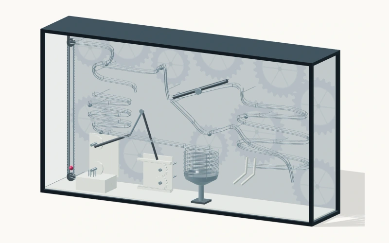
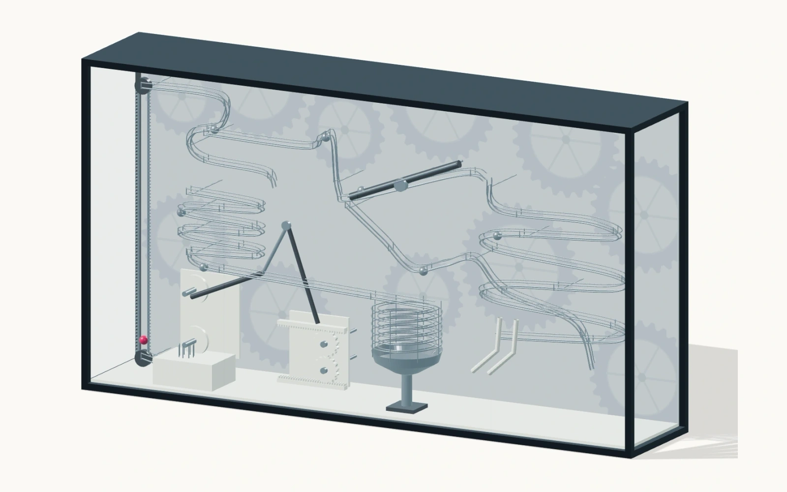
The eighteen-second Gear Wall video orbits an archived 3D design. Inspect geometry and arrangement.
Locate the wall structure
Compare frame and route placement as the camera moves.
Separate mechanism types
Identify gears, linkages and spiral ball routes. Curved routes are not automatically gear connections.
List what needs confirmation
Identify where drawings or close-ups are needed to establish tooth counts, shaft connections and input.
About this video reference
3D design preview · Camera orbit. It establishes no physical gear rotation, ball travel, measured ratio or completed installation. The worked examples are not parameters of this design.
01 / EXPLAINING THE IDEA
Name the driver before dividing
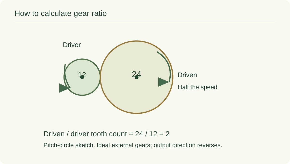
The driver receives the input; the driven gear receives motion through the mesh. Here, gear ratio means input speed divided by output speed, using positive magnitudes. State the convention: the opposite order describes its reciprocal.
A 3:1 ratio means three input turns for each output turn. A 1:3 ratio means one input turn for three output turns. Name the input, output and order to avoid ambiguity.[1][3]
02 / EXPLAINING THE IDEA
Why tooth counts determine the speed ratio
As properly meshing gears turn, teeth pass through the mesh in matching numbers. A driver with 20 teeth advances 20 tooth positions in one revolution. A driven gear with 60 teeth has completed only one-third of a revolution when those positions have passed.
For ordinary external spur gears, use compatible tooth forms and the same module: pitch diameter divided by tooth count. Tooth counts then represent pitch-diameter ratios. Outside diameter is different, so measuring across tooth tips is a poor substitute for counting teeth.[2]
03 / EXPLAINING THE IDEA
An ideal 20-tooth and 60-tooth example
Imagine a 20-tooth driver running at 120 revolutions per minute and transmitting 0.50 newton metre of torque to a 60-tooth driven gear. The ratio is 60/20 = 3. Output speed is 120/3 = 40 revolutions per minute. With steady motion and no losses, output torque is 0.50 × 3 = 1.50 newton metres.
These are invented teaching values, not tooth counts, operating speeds or load ratings for Gear Wall. A real specification also considers loads, materials, bearings and the drive arrangement.[1]
| Quantity | Hypothetical input | Ideal output |
|---|---|---|
| Teeth | 20 | 60 |
| Speed | 120 rpm | 40 rpm |
| Transmitted torque | 0.50 N·m | 1.50 N·m |
| Rotation direction | Clockwise | Counterclockwise |
04 / EXPLAINING THE IDEA
More torque comes with less speed
Torque measures a turning effect. At steady speed, an ideal gear transmission transfers the same power into and out of the pair. Rotational power is torque multiplied by angular speed. Reducing speed by a factor of three therefore permits three times the transmitted torque in the ideal case.
Real losses leave less output power available. The tooth-count ratio predicts relative motion, but it does not establish tooth strength, allowable hand force or service life. Those require separate design decisions.[1][3]
05 / EXPLAINING THE IDEA
An idler changes direction, while compound stages can change ratio
Each external mesh reverses rotation. Insert one simple idler between a driver and a driven gear and there are now two reversals: input and output rotate in the same direction. In a simple fixed-axis train, the idler's tooth count cancels from the overall speed-ratio calculation.
For example, 20 teeth driving a 30-tooth idler driving 60 teeth still gives (30/20) × (60/30) = 3. A compound train differs: two gears fixed to one shaft rotate together. Successive stage ratios then multiply, so the tooth counts on that shared shaft need not cancel.[2][3]
06 / EXPLAINING THE IDEA
Use the Gear Wall preview to ask better questions
The preview combines a wall structure with gears, linkages and spiral routes. It helps compare their arrangement as the camera orbits. It does not show a running gear train: apparent movement caused by the camera cannot establish gear turns.
Before calculating, identify input, output, connecting shafts and meshes from a suitable drawing or demonstration. Nearby wheels or ball routes need not share a gear train.
07 / EXPLAINING THE IDEA
Make the ratio a prediction learners can check
On a suitable teaching mechanism, mark reference positions and predict the output after one input turn. Compare turns and directions, then add an idler to isolate its role.
Bicycle gearing offers a familiar extension. The Exploratorium explains ratios using front and rear sprocket teeth. Carry over the tooth-count reasoning, but discuss direction separately: a chain joins those sprockets rather than a direct external mesh.[4]
Common questions.
Which tooth count goes on top?
For the reduction-ratio convention used here, divide driven teeth by driver teeth. For output speed, multiply input speed by driver teeth divided by driven teeth. Name the convention each time.
Can a larger simple idler create a greater reduction?
Its size changes the intermediate speed and layout, but its tooth count cancels from the overall ratio of a simple fixed-axis train. Adding an external mesh also changes direction.
Can the Gear Wall preview verify its operating ratio?
No. This camera orbit shows an archived 3D design. Verified tooth counts, connections and a suitable operating demonstration or drawing are needed before assigning a product-specific ratio.
SCIENCE & FURTHER READING
Follow the sources.
Read the original scientific explanations and teaching resources behind this article.
- UC San Diego MAE 3 — Gear Ratios
Defines the input/output speed convention and derives the ideal speed, torque and power relationships with stated assumptions.
- Carnegie Mellon University — Introduction to Mechanisms, Chapter 7: Gears
Pitch circles, module, compatible meshing, simple idlers, direction and compound trains.
- Carnegie Mellon University — Introduction to Mechanisms, Chapter 2: Mechanisms and Simple Machines
Driver/driven terminology, turn-count reasoning, compound arrangements and the distinction between ideal and real machines.
- Exploratorium — Science of Cycling: Drives & Gears
Uses sprocket tooth counts to explain bicycle gearing. Its chain-drive example is distinguished from a direct external gear mesh.
Editorial: Exhibit Engineers science & exhibit team. Scientific references are cited for the explanations; product configuration details follow the linked exhibit records.